Application Spotlight
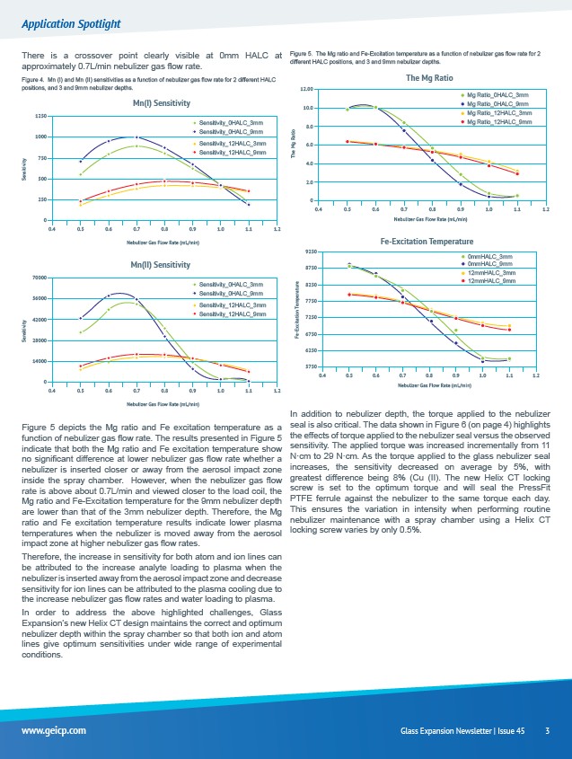
There is a crossover point clearly visible at 0mm HALC at
approximately 0.7L/min nebulizer gas flow rate.
Figure 4. Mn (I) and Mn (II) sensitivities as a function of nebulizer gas flow rate for 2 different HALC
positions, and 3 and 9mm nebulizer depths.
Mn(I) Sensitivity
0.5 0.6 0.7 0.8 0.9 1.0 1.1 1.2
Nebulizer Gas Flow Rate (mL/min)
Sensitivity_0HALC_3mm
Sensitivity_0HALC_9mm
Sensitivity_12HALC_3mm
Sensitivity_12HALC_9mm
Sensitivity
0.4
1250
1000
750
500
250
0
Mn(II) Sensitivity
0.5 0.6 0.7 0.8 0.9 1.0 1.1 1.2
Nebulizer Gas Flow Rate (mL/min)
Sensitivity_0HALC_3mm
Sensitivity_0HALC_9mm
Sensitivity_12HALC_3mm
Sensitivity_12HALC_9mm
Sensitivity
0.4
70000
56000
42000
28000
14000
0
Figure 5 depicts the Mg ratio and Fe excitation temperature as a
function of nebulizer gas flow rate. The results presented in Figure 5
indicate that both the Mg ratio and Fe excitation temperature show
no significant difference at lower nebulizer gas flow rate whether a
nebulizer is inserted closer or away from the aerosol impact zone
inside the spray chamber. However, when the nebulizer gas flow
rate is above about 0.7L/min and viewed closer to the load coil, the
Mg ratio and Fe-Excitation temperature for the 9mm nebulizer depth
are lower than that of the 3mm nebulizer depth. Therefore, the Mg
ratio and Fe excitation temperature results indicate lower plasma
temperatures when the nebulizer is moved away from the aerosol
impact zone at higher nebulizer gas flow rates.
Therefore, the increase in sensitivity for both atom and ion lines can
be attributed to the increase analyte loading to plasma when the
nebulizer is inserted away from the aerosol impact zone and decrease
sensitivity for ion lines can be attributed to the plasma cooling due to
the increase nebulizer gas flow rates and water loading to plasma.
In order to address the above highlighted challenges, Glass
Expansion’s new Helix CT design maintains the correct and optimum
nebulizer depth within the spray chamber so that both ion and atom
lines give optimum sensitivities under wide range of experimental
conditions.
Figure 5. The Mg ratio and Fe-Excitation temperature as a function of nebulizer gas flow rate for 2
different HALC positions, and 3 and 9mm nebulizer depths.
The Mg Ratio
0.5 0.6 0.7 0.8 0.9 1.0 1.1 1.2
Nebulizer Gas Flow Rate (mL/min)
Mg Ratio_0HALC_3mm
Mg Ratio_0HALC_9mm
Mg Ratio_12HALC_3mm
Mg Ratio_12HALC_9mm
The Mg Ratio
0.4
12.00
10.0
8.0
6.0
4.0
2.0
0
Fe-Excitation Temperature
0mmHALC_3mm
0mmHALC_9mm
12mmHALC_3mm
12mmHALC_9mm
0.5 0.6 0.7 0.8 0.9 1.0 1.1 1.2
Nebulizer Gas Flow Rate (mL/min)
Fe-Excitation Temperature
0.4
9250
8750
8250
7750
7250
6750
6250
5750
In addition to nebulizer depth, the torque applied to the nebulizer
seal is also critical. The data shown in Figure 6 (on page 4) highlights
the effects of torque applied to the nebulizer seal versus the observed
sensitivity. The applied torque was increased incrementally from 11
N·cm to 29 N·cm. As the torque applied to the glass nebulizer seal
increases, the sensitivity decreased on average by 5%, with
greatest difference being 8% (Cu (II). The new Helix CT locking
screw is set to the optimum torque and will seal the PressFit
PTFE ferrule against the nebulizer to the same torque each day.
This ensures the variation in intensity when performing routine
nebulizer maintenance with a spray chamber using a Helix CT
locking screw varies by only 0.5%.
www.geicp.com Glass Expansion Newsletter | Issue 45 3
/www.geicp.com